Vision prototype photo

Vision prototype photo
This is the Vision prototype designed/built by Steve Rahm in USA. and still being supported by Pro Composites Ltd. in USA. The aircraft is a 2 seat side by side, scratch built from a series of manuals. Built entirely of fiberglass and carbon cloth material the builder needs to know or learn some of the easy basics of composite construction. Building began Feb. 1998 in my spare time with 7 years where no building was possible. Building Hours at February 28, 2022: 4248.--------------------------------------------------------------------------------------------------------------------------------Some short videos of flights are at: https://www.youtube.com/channel/UCfxJXIwvmfNlNF3gwplFw7Q

Friday, July 30, 2021

June and July progress

Month of July I got a bit more done between some flying around for fun meeting up with friends at various airports.  I bought a ARTEX 406 ELT for the plane and got it all installed.  The black box is my Dynon ADAHRS unit with networking cable installed.  All of this is located just behind the aft bulkhead of the baggage compartment.  Green tube is the push/pull to the elevator with a intermediate idler arm.  The octagon is my ground plane for my Transponder antenna.
Installed my Flap controller unit which controls my flaps settings for 5 degrees, 14 and full down at 34 degrees.  Now I am beginning the large panel wiring process.

Below is my custom built fiberglass panel which has 4 removable sub panels for instruments.


Sunday, May 30, 2021

May progress

May and June not much to report.  The Rudder and Elevator were installed on the airplane and all of the bolts and nuts of the proper sizes installed. 

The tail wheel install was completed with all bolts-nuts and safety wired.  I made up two interface stainless connector cables to tie in the tail wheel steering springs.


Friday, May 14, 2021

ADAHRS Mounting To new Location

 May 14 2021, Update:  I had to move the ADAHRS unit to a new location because testing revealed that there was magnetic interference in the area under the pilot's seat due to the proximity of the installed Auto Pilot servos.  The ADAHRS is now installed aft of the baggage compartment.

December 26 2020, I have a Dynon system and so a Adahrs which must be installed in a magnetic free area.  It must also be oriented in a forward facing configuration and most difficult, must be installed in a level plane fore/aft and laterally in the fuselage when aircraft in level attitude.  I chose to install under the pilots seat for reasons of easy access to reset the level attitude if required.  I had to build up a triangular wood ramp for the Adahrs unit to mount onto as the floor is at a odd angle fore/aft.  This so it would be level when in a level flight attitude.  I then made a aluminum plate to bond to the  wood base  The Adahrs unit will screw onto this using Nylon or Stainless screws and nuts.  I built up the wood base to a level line matching the longerons and then bonded the wood to the floor.  If it is out of level in either direction I can shim the Adahrs unit to make level after seeing what results I get in flight.


Monday, April 5, 2021

Fiberglass Wing Tips and Panel mod

 April 5 2021

I bonded blocks of soft foam onto the ends of the wing tips and then began to shape a simple tip which was pleasing enough to me.  I then covered the pink soft foam in packing tape as a release agent for the fiberglass.   The foam being so soft is great for carving but is delicate and requires care when touching it.  Sanding the surfaces of the upper and lower tip edges gave a good bonding surface.   I laid  up the upper and then the lower surfaces first because I knew that it was going to be difficult forming the compound curves around the tip.  This way I would have a firm surface to work the edges of the outer cloth onto the hardened upper and lower surfaces.  Because the outer three layers now cause a small step in the surface I will have to fill with filler.  The foam blocks were attached with two part auto body putty dabs placed randomly over the outer wing rib.  The tip came off the mold quite easily as the release tape worked excellent and the foam broke away from the auto body putty.  It was a bit of work to get them off though and I had to work tools between the fiberglass and the release tape before pounding on the surface to get the foam to break free.  The foam came out of the inside of the tip after removal.  They can be pried out or the whole foam plug can be dug out later if it is difficult.  One of mine came out very easy and the other needed persuading and a few chunks of foam broke out.


Then I fabricated L shaped flanges which will be the attach points by laying up four layers of glass along the edge of a piece of wood with packing tape on it.  The flanges were trimmed to 3/4" by 3/4" and marked into one inch sections where I installed a nut plate onto each one inch section.  These flanges were bonded onto the outer face of the outer  rib, 7 on top and 7 along the bottom using structural adhesive.


The tips were attached and holes drilled at each nut plate location.  The new tips overlap the aileron and so a piece had to be trimmed off to allow the aileron to move.  Once trimmed I made a rib to fit inside the tip at the aft end to add rigidity and to close off airflow into the open aft end of the wing tip.  This was bonded on with a thin layer of epoxy/flox.


The instrument panel central radio section was modified for a Dynon radio head and the far right section modified to allow the ELT remote switch and 3 pull off fuses for the Flaps, Auto Pilot and Avionics.  Panel sections were then painted in semigloss black.


Sunday, March 7, 2021

Engine Silicone Baffling and Auto Pilot Servo mounting

 March 7 2021

A large part of my time this month was spent fabricating the Silicone seal baffle around the top of the engine.  I set up a system of sliding wooden pieces to identify the height from metal baffle to inside surface of the cowling.  Then I was able to determine the width of silicone to use.  The standard 3 inch stuff worked out to fit well.  I decided I wanted all silicone to be removable and so installed on #6 nuts and bolts with a aluminum back plate.  This also allowed me to use pieces with fewer separations as I did not have to account for each separation in the aluminum baffling material below the silicone.


I began building a two brackets for the autopilot servos, the roll unit going under the passenger seat and the pitch servo insider the center console.  A lot of test fitting was required and the aileron and elevator push pull tubes were disconnected and reconnected many times to find the right fit.


The position of the A-pilot units ended up to be too close to the ADAHRS unit with a magnetometer inside it so I made a new bracket for the ADAHRS and positioned it in the rear just behind the baggage compartment.


Wednesday, February 24, 2021

Air Intake to Air Filter Box

 February 24 2021

I got into work on calculating how I could get the air intake on the front of the lower cowling to mate with the intake opening of the Air Filter Box.  Numerous friends had mentioned it was a tricky bit of maneuvering to get the lower cowling on and mate the air intake.  A friend with a RV mentioned I could cut off the front of the cowling intake and make it removable.  This sounded perfect, so I did some internet research and found some guidance.  I decided to make the front intake removable with an attached tube entering the Filter box.

Below after the foam was shaped the difficult part was getting the 3 layers of glass cloth lined on the inside of the opening.

Glassing of tube completed, time to cut off the intake after finding a pleasing cut line.


I trimmed the new fiberglass tube to about 4 inches long.
Using tongue depressors as spacers I bonded the intake back on using auto body putty.  Then working on the inside of the lower cowling I laid up 3 layers of glass for a flange.  The gap where the cut line was will later be filled using micro.

After trimming, nut plates were mounted in the newly formed flange.  I should have made the upper nut plates at 10 oclock and 2 oclock as it was hard to get the rivet squeezer placed at the 12 position.
Hand carved a piece of foam until it was a the proper shape of air intake and of the Filter box.  Covered the foam with packing tape and then temp. bonded into the air intake unit.

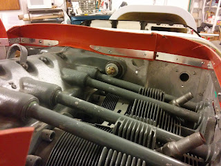
Very happy with the finished product, it makes a beautiful fit to the filter box entry mounted on the engine.


Friday, January 8, 2021

Oil Filler Access Door

 January 8 2021

The oil filler and dipstick access was started by making a Splash coat of  3 layers of carbon fiber and then laying that onto the top surface of the engine cowling.  I identified the location and size of the door, marked it on the cowling with a sharpie and taped over area with packing tape.  This was left to harden for a couple of weeks while I did other jobs.  I spoke with a friend who builds Vans RV's on the field and he suggested I build a hidden hinge style for better esthetics.  I was happy to go this route and had a great example in one of his planes to model mine upon.  The splash coat is to form a new oil door from that is a perfect match to the curvature of that location of the cowl.  I removed the splash coat and then carefully cut out the shape of oil door I wanted.  Then I cut and trimmed the Carbon splash coat to exactly fit the door opening I just made.  I taped the inside of the oil door in packing tape then taped the new door into place on the outer surface of cowling.  I then made up fiberglass strips for flanges and applied to the sanded inside surface of cowling, these will support the oil door.  Afterwards trimmed down the flanges and installed the 2 Milspec quarter turn fasteners which will it closed.  I then bent up the aluminum curved hinge adapter out of .062 thick aluminum.  Trimming off the excess aluminum (right hand edge in photos) to get a good fit, finally drilling and cleco in place.  I am only riveting the outer ends of the piano hinge and other holes all have a dab of structural adhesive.  The hinge onto the adapter will have 5 rivets.